Home / Products / Low Voltage Circuit Breaker / Air Circuit Breaker (ACB) / QW1 400A to 6300A Air circuit breaker
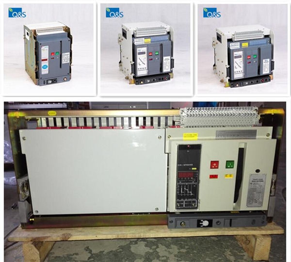
QW1 series universal Air circuit breaker(hereinafter referred to as breaker)is suitable for the circuit of AC 50Hz with rated voltage 400V, 690V and rated current up to 6300A. It is mainly used to distribute electric energy and protect circuits and power-supply equipment from overload, under-voltage, short-circuit and single-phase earthing. with intelligentized and selective protection functions, the breaker can improve the reliability of power supply, and avoid unnecessary power failure. The breaker is applicable for power stations, factories, mines(for 690V) and modern high-buildings, especially for the distribution system of intelligentized building. This breaker conforms to IEC60947-2 and GB14048.2 and CE.
description
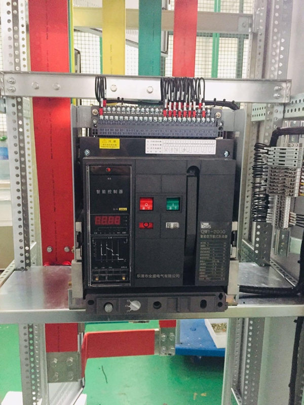
QW1-3200 QW1-4000
Size A, B and C;
From 400 A to 6300 A.
Applications and functions
Incoming-feeder and outgoing-feeder function in distribution systems
Switching and protecting large powers, motors, capacitors, generators, transformers, busbars and cables
Overload protection
Short-time delayed short-circuit protection
Instantaneous short-circuit protection
Used in building, industry, energy and infrastructures
Features
Modular design
Components like auxiliary releases, motorized operating mechanisms, electronic releases, current sensors, auxiliary circuit signaling switches, automatic reset devices, interlocks and engagement operating mechanisms can all be exchanged or retrofitted in the back ground, thus allowing the circuit breaker to be adapted to new, changing required.
Communication
The use of modern communication-capable circuit breakers opens up completely new possibilities in terms of start-up, parameterization, diagnostics, maintenance and operation. This allows varieties of ways of reducing costs and improving productivity in industrial plants, buildings and infrastructure projects.
Easy wiring by different terminals
A wide variety of terminals are offered, to guarantee an optimal solution for connection to the power circuit under different applications.
Technical specifications
Standard: IEC 60947-2
Number of poles: 3-pole, 4-pole
Rated operational voltage Ue: 400 V, 690 V
Rated insulating voltage Ui: 1000 V
Rated frequency: 50 - 60 Hz
Rated impulsed withstand voltage Uimp: 12 kV
Neutral pole current-carrying capacity for 4-pole CBs: 100% In
Version: Fixed version, Withdrawable version
Feature details:
○ Measurement and operation monitoring
Real-time measurement of the power grid operating parameters, such as: frequency power factor active power: real-time indication of operating status, such as: fault status, alarm status system self-diagnostic status, normal operation.
○ Query function
Running parameter query, protection parameter setting value query, history fault record query, self-diagnosis fault information query and power grid measurement parameter query and other functions.
○ Parameter setting function
The following protection parameters can be set directly on the front panel of the controller: current value and time value of long-time overload protection, inverse current value of short-circuit short delay protection, definite time current value and time value, instantaneous protection current value, Current value and time value, N phase protection setting value, grounding current or residual current protection current value, time value and inverse time coefficient, unbalance value and time value of current unbalance protection, harmonic influence coefficient.
The following operations can be performed on the front panel of the controller: System clock adjustment (only when this function is selected), and tuning the internal parameters of the system that can be set by all programmer (without programmer, but need password).
○ Programming interface function
It provides the interface with the programmer. It can modify some specific parameters, such as the function setting of signal output contact, the way of voltage measurement, system clock, protection characteristic curve, thermal memory function, communication address and communication baud rate.
○ Communication network function (this function is only available for H type function controller)
Controller provides standard RS485 interface, Modbus or Profibus-DP or DeviceNet protocol can be used to achieve data transmission to meet the different monitoring system "four remote" requirements.
○ Test function
Test function sub-instantaneous tripping simulation test and non-tripping simulation test two kinds:
(1) instantaneous trip simulation test: circuit breaker can be instantaneous action of the tripping test, after the action can display the circuit breaker's inherent action time.
(2) non-tripping simulation test: select the simulation test current system for non-tripping test, alternately after the test shows the test current and the test current in the system delay time and simulation test fault category.
○ Self-diagnosis function
The controller itself appears some fault diagnosis alarm.
○ Fault clock function (optional)
Used to record the time of failure, can record the occurrence of the failure of the year, month, day, hours, minutes and seconds. (Can record up to 8 times)
○ Historical data recording function (optional)
Used to record the four-phase current, three-phase voltage, frequency, power, power factor, active power, recorded every half hour once, can be recorded for three months.
○ Load monitoring protection function
Load monitoring is to control the different load of circuit breaker, in order to guarantee the power supply of main load as far as possible. Load monitoring can be used to pre-alarm, can also be used to control the load branch. The controller is programmable to output two passive signal contacts for load monitoring.
○ MCR on-off and over-limit trip function (optional)
On-off is the fault that the grid is in fault status before the circuit breaker closes. At the moment of closing, a current greater than the set value of MCR is generated. The controller breaks the circuit breaker in an instantaneous way through the analog circuit. This function only in the closing moments 1OOms) play a role. Over-limit trip refers to the circuit breaker in normal operation, when the short-circuit current exceeds a certain value (usually the circuit breaker limit current), the controller through the analog circuit to instantaneous way to break the circuit breaker, this function is not instantaneous set value Impact.
○ Remote, local and set position setting functions (H-type controller only) The controller can set the three status positions of "remote control", "local" and "setting", adopt digital position lock, Operation to achieve, for the network when the permissions set to "remote control", through the host computer to achieve the four remote control operation.
M-type and H-type difference:
M-type intelligent controller and H-type intelligent controller in the function of the difference there are two points:
(1) The function table function of the M-type controller is optional, while the H-type controller does not need to be selected for the basic configuration.
(2) H-type controller has networking and remote local control and set the three-position selection function, while the M-type controller does not have.
○ Communication protocol
Modbus RTU is included and can be transferred to ProfibusDP or DeviceNet via an external module.
Operating Performance of Circuit Breakers
Structure Overview
○ Drawer type circuit breaker
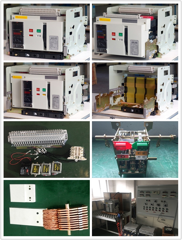
Drawer-type circuit breaker from the circuit breaker body and drawer seat composition. Drawer seat on both sides of the rails, rails on the activities of the guide plate, the circuit breaker body frame on the left and right guide plate. Drawer-type circuit breaker through the circuit breaker body on the bus into the drawer seat bridge contacts to connect the main circuit. Shake the handle of the lower beam of the drawer holder to realize the three working positions of the drawer circuit breaker (there is a position indication beside the swing handle), and there are three position locks to more reliably determine the position and prevent the body from slipping.
"Connection" position: the main circuit and the secondary circuit are connected.
"Test" position: The main circuit is disconnected and separated by an insulating barrier. Only the secondary circuit is switched on, and the necessary operation test can be performed.
"Separation" position: the main circuit and the secondary circuit all disconnected. In the "separation" position To remove the circuit breaker body, you must remove the swing out of the handle.
Drawer type circuit-breakers have mechanical interlocks that allow the circuit-breaker to be closed only in the connected position or in the test position. In the middle of the connection and test can not be closed.
○ Interlocking mechanism
The interlocking mechanism is installed on the right side plate of the circuit breaker, and the cable tie is interlocked (Figure 8). The circuit breaker is interlocked with the interlocking circuit breaker (Figure 9). When one of the circuit breakers is in the closing state, The other can not be closed, interlocking institutions installed by the user.
Categories of Intelligent Air Circuit Breaker(ACB)
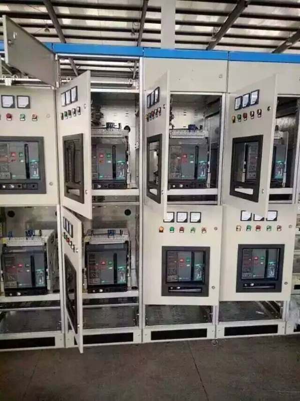
1. Our air circuit breaker can be of two installation types: fixed type and draw-out type
2. Number of poles: 3 pole and 4 pole
3. Operation type: manual operation, auto operation
4. Trip types: Intelligent controller, under voltage instant ( or time delay type) trip and shunt trip
5. Intelligent controller categories: L type(basic type), M type( Standard type), and H type ( communication type)
Normal Working Conditions of intelligent Air Circuit Breaker(ACB)
1. The ambient temperature of our intelligent circuit breaker should be within -5°Cto +40°C. The average temperature should not be more than +35°C(except for customized designs)
2. The altitude should be below 2000M.
3. The relative humidity should not be more than 50% at +40°C, the upper temperature limit. At lower temperatures, higher humidity is allowed e.g 90% at 20°C. Dew that is formed during temperature variation should be eliminated, to increase its durability.
4. Pollution grade: class 3
5. The following have an installation grade of IV: main circuit, absent voltage release coil, power transformer primary coil. Other auxiliary circuits and controls have a mounting grade of III.
6. The circuit breaker should be installed according to the manual. The vertical tilt angle should not exceed 5 degrees.
7. if the air circuit breaker is installed in a small compartment of the switch board, the protection grade is up to IP40. If it is then fitted with a door frame, the protection grade is up to IP54.
Structure Characteristics of Intelligent Air Circuit Breaker(ACB)
1. Our intelligent air circuit breaker can be of a fixed type and draw-out type. The fixed type air circuit breaker is installed within a special drawer to become a draw-out type breaker. Our circuit breaker consists of a contact system, and arc-extinguishing system, operating mechanism, current transformer, intelligent controller and auxiliary switches, secondary plug and socket, under voltage and shunt releases. The draw-out type air circuit breaker has a holder that is made up of right and left side plates, base, beams, etc.
2. Contact system
It adopts integrated contact system, including the main contact and arc contact. The contact is made of high quality material, which does not lead to high temperatures even when it is breaking short circuit current. The contact system is of parallel connection, which reduces the electrical-dynamic repulsion force and improves electric steadiness.
The distance between the moving and static contact is much greater than 18mm as it is required. This is in full compliance with safety requirements.
Note: "Trip" lock device for breaker is optional, the isolating switch is a necessary.
3. Arc-extinguishing chamber
Each pole has an arc-extinguishing chamber, which works to separate and isolate each electrode. The arc extinguishing chamber is enclosed within the insulating base of the intelligent air circuit breaker, which enforces the mechanical strength of arc extinguishing chamber wall and avoids breakage when it is breaking a large short circuit current.
4. Operating mechanism: manual and automatic mechanism
The operating mechanism is located at the front of the intelligent air circuit breaker. It adopts a five-link, trip free structure. It is available with energy storage. The breaker can be closed instantly. The stored energy can be released by a hand-operated button or closing electromagnet. The motor driven mechanism is integrated: consists of an energy storage shaft and main shaft which are connected with concave and convex parts. It is easy to assemble or disassemble.
5. Intelligent controller
6. Drawer holder
The drawer holder of our intelligent air circuit breaker consists of right and left guide rail side plates, base and cross arm. A boosting device and an indicator are fitted to the base. A static contact auxiliary circuit is installed at the top of the drawer holder. The bridge type main circuit contacts are safety separated by a plate at the front.
7. Three positions of the breaker in the drawer
--\"ON" position: Both the main circuit and the auxiliary circuit are connected. The separation plate is open.
--\"Test" position: the main circuit is disconnected. The separation plate is closed. Only the auxiliary circuit is connected. Tests can be made in this mode.
--\"OFF" position: both the main and the auxiliary circuits are disconnected. The safe separation plate is closed.
Installation and usage
Installation Unload the breaker from the soleplate of package-box. if it is drawer type, firstly pull out the handle from under the drawer-base of breaker, and plug it into the hole on central section of plastic cover under the drawer-base crossbeam, anticlockwise turns the handle, breaker body will slowly slide along the outside of drawer-base. When the guide-rod points to separated position and handle can't be rotated any longer, pull out the handle and firmly grasp the aluminum handle on drawer-base, pull out the breaker body and remove it form drawer-base Check the insulation resistance with a 500V megger, resistance should not be less than 20MQ when ambient temperature is 205and relative humidity is 50%- 70%.otherwise have it drying. Put the breaker(fixed-type) or drawer-base(drawer type) onto the installation- bracket, and make it fixed, directly connect the bus wire of main circuit to the bus wire of fixed-type circuit breaker, alternatively put breaker body onto the guild rail of drawer-base.
Plug the place, then connect the bus wire of main circuit to bus wire of drawer-base. wiring the secondary circuit according to electric principle diagram. Note: something like bolts, nuts.gaskets shouldn't be left inside the drawer-base to avoid being blocked. Usage and operation Check the rated voltage of the following components whether conforms to the power voltage or not. such as under voltage release, shunt release closing electromagnet, motor-driven mechanism and intelligent controller Maintenance Check the technical index on time or and some lubricating oil., etc. This breaker structure is arranged vertically and modular composition with each function=cell separated, which make the maintenance easy.it has compact structure, reliable operation and strong free maintenance capability. Please check the technical parameters on the nameplate accordance with the requirements of order before installation.
Specifications of Q&S brand QW1 series Intelligent Air circuit breaker
| Type | QW1 -2000 | QW1-3200 | QW1-6300 | ||
| Pole | 3P, 4P | 3P, 4P | 3P, 4P | ||
| Using category | B | B | B | ||
| Rated current In | A | 630, 800, 1000, 1250, 1600, 2000 | 2000, 2500, 3000 | 4000, 5000, 6300 | |
| Rated frequency | Hz | 50/60 | 50/60 | 50/60 | |
| Rated operation voltage Ue | V | 400 690 | 400 690 | 400 690 | |
| Rated insulation voltage Ui | V | 800 | 800 | 800 | |
| Arcing distance | mm | 0 | 0 | 0 | |
| Rated impulse withstanding voltage Uimp | V | 8000 | 8000 | 8000 | |
| Rated operation short circuit breaking capacity Ics(O-t-CO-t-CO) | 400V | ka | 50 | 80 | 100 |
| 690V | ka | 40 | 50 | 75 | |
| Rated limiting short circuit breaking capacity Icu(O-t-CO) | 400V | ka | 80 | 100 | 120 |
| 690V | ka | 50 | 65 | 85 | |
| Rated short circuit closing capacity Icm | 400V | ka | 176 | 220 | 264 |
| 690V | ka | 105 | 143 | 187 | |
| Rated short time withstanding current Icw(O-t-CO, AC400V 0.4s) | 400V | ka | 50 | 65 | 85 |
| Operation life | per hour | Times | 20 | 20 | 10 |
| Electrical | Times | 1000 | 500 | 500 | |
| Mechanical | Times | 10000 | 5000 | 5000 | |
| Full breaking time | ms | 20~30 | 20~30 | 20~30 | |
| Full closing time | ms | 55~70 | 55~70 | 55~70 | |
| Power consumption | 3P | W | 360 | 1200 | 2000 |
| 4P | W | 450 | 1750 | 2300 | |
| Resistance of each pole | Fixed type | μ Ω | 11 | 9 | - |
| Draw out type | μ Ω | 20 | 14 | 10 | |
| Dimensions(L*W*H) | 3P fixed type | mm | 362*323*402 | 422*323*402 | |
| 3P draw out type | mm | 375*461*452 | 435*471*452 | ||
| 4P fixed type | mm | 457*323*402 | 537*323*402 | ||
| 4P draw out type | mm | 470*461*452 | 550*471*452 | ||
| Approximate weight | 3P fixed type | kg | 41 | 55 | |
| 3P draw out type | kg | 71 | 95 | 245 | |
| 4P fixed type | kg | 51.5 | 65 | ||
| 4P draw out type | kg | 86 | 115 | 260 |
Structure:
Drawer type breaker and fixed type breaker
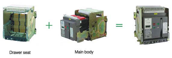
The breaker consists of body and drawer base. inserting the body into the drawer base, thus make the drawer-type breaker

Making the secondary circuit power, the motor-driven mechanism can store energy automatically until hearing the click and energy stored "indicating on the panel. otherwise press the storage handle for 6 times until hearing the click and the indicator display energy stored" and the closing operation can be realized either by closing electromagnet or manual button.
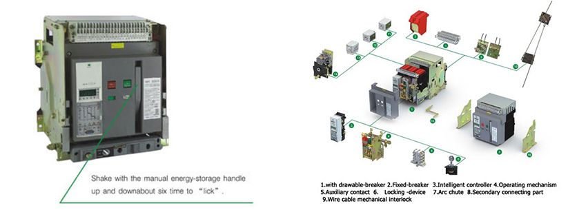
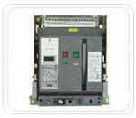
QW1-2000
Main technical parameter:
| Rated ultimate short circuit breaking capacity(KA) | lcu=80KA 400V 50KA 690V lcs=lcw=50KA 690V 40KA 690V | |
| Rated current in (A) | 400 630 800 1000 1250 1600 2000 | |
| Number of poles | 3, 4 | |
| Rated voltage ue(V) | 400V, 690V | |
| Rated insulation voltage Ui (A) | 1000V | |
| Rated current of N-pole IN(A) | 50%In, 100%IN | |
| Fixed disconnection time | 23-32Ms | |
| Intelligent controller | standard type(M) | |
| Communication type(H) | ||
| Operation performance | Electric life | 500 |
| mechanical life | Non-maintenance 2500 | |
| Maintenance 10000 | ||
| Connection pattern | Horizontal, vertical | |
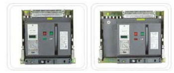
QW1-3200 QW1-4000
| Rated ultimate short circuit breaking capacity(KA) | lcu=100KA 400V 80KA 690V lcs=lcw=80KA 400V 40KA 690V | |
| Rated current in (A) | 2000 2500 3200 4000 | |
| Number of poles | 3, 4 3 | |
| Rated voltage ue(V) | 400V, 690V | |
| Rated insulation voltage Ui (A) | 1000V | |
| Rated current of N-pole IN(A) | 50%In, 100%IN | |
| Fixed disconnection time | 23-32Ms | |
| Intelligent controller | standard type(M) | |
| Communication type(H) | ||
| Operation performance | Electric life | 500 |
| mechanical life | Non-maintenance 2500 | |
| Maintenance 10000 | ||
| Connection pattern | Horizontal, vertical | |
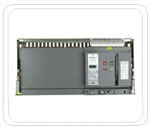
QW1-6300
| Rated ultimate short circuit breaking capacity(KA) | lcu=120KA 400V 80KA 690V lcs=lcw=100KA 400V 60KA 690V | |
| Rated current in (A) | 4000 5000 6300 | |
| Number of poles | 3, 4 3 | |
| Rated voltage ue(V) | 400V, 690V | |
| Rated insulation voltage Ui (A) | 1000V | |
| Rated current of N-pole IN(A) | 50%In, 100%IN | |
| Fixed disconnection time | 23-32Ms | |
| Intelligent controller | standard type(M) | |
| Communication type(H) | ||
| Operation performance | Electric life | 500 |
| mechanical life | Non-maintenance 2500 | |
| Maintenance 10000 | ||
| Connection pattern | Horizontal, vertical | |
